When the model is solved, the results are separated into
material specific design results and generic results. The generic
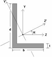
Depending on whether a single angle has been fully restrained against rotation or not, it will either behave about its geometric axes or its principal axes. This behavior can be controlled by correctly specifying the unbraced lengths for the angle. In the diagram below the z and y axes are the geometric axes. The z' and y' are the principal axes. The y' axis is considered to be the weak axis for principal behavior, and the z' is considered to be the strong axis.
The orientation of the shape is defined using the local y and z axes shown in the above diagram, but for principal axis behavior the bending calculations are done with respect to the y' and z' axes shown (the principal axes). The y' axis is the axis of minimum 'I' and the z' axis is the axis of maximum 'I'. RISA calculates the angle "α" and transposes the moments as shown below:
Mz' = Mz * cos(α) + My * sin(α)
My' = -Mz * sin(α) + My * cos(α)
Note
The Deflection Results Spreadsheet presents the deflections for beam members and may be accessed by selecting Deflection on the Results Menu. The spreadsheet has three tabs: Relative Standard, Relative Alternate, and Absolute.
Relative deflections are measured from the deflected end points of the beams. Absolute deflections, however, include the deflection of the beam end points. The pull down list at the top of the spreadsheet allows you to toggle between floors.
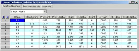
The sign convention is such that positive deflections are downward. The deflections are calculated at 100 locations along each beam for each load category and the maximum deflection and deflection ratio are displayed. See Results - Locations of Calculations for more information.
The Beam Label column displays the beam label.
The Camber column displays the camber required for the percentage of pre-composite dead load specified in the Model Settings. To modify camber requirements see Member Design Rules, or you can manually enter a specific camber value on the Hot Rolled Steel tab of the Members spreadsheet. For an overview on camber see Hot Rolled Steel - Design.
Note
These columns display the maximum deflection along the member due to the total, unfactored pre-composite dead load. This includes the deflection due to beam self weight, deck self weight, deck construction DL and pre-composite DL minus the effect of camber. The PreDL column gives the relative deflection on the beam from its supporting members. The PreDL Ratio is the length of the member divided by the maximum PreDL deflection.
These columns display the maximum deflection along the member due to total unfactored dead load. This includes the deflection due to beam self weight, deck self weight, pre-composite DL and post-composite DL minus the effect of beam camber. The DL column gives the relative deflection on the beam from its supporting members. The DL Ratio is the length of the member divided by the maximum DL deflection.
These columns display the maximum deflection along the member due to total unfactored live load. This will be due to the summation of all of the various live load categories which can act concurrently. This includes Live Load, Live Load Special, and one of the roof loads (Roof Live Load, Snow Load or Rain Load). The LL column gives the relative deflection on the beam from its supporting members. The LL Ratio is the length of the member divided by the maximum LL deflection.
Note
These columns display the maximum deflection along the member due to the sum of total unfactored DL and total unfactored LL. The DL+LL ratio is calculated as the length of the member divided by the maximum DL+LL deflection.
The Relative Alternate tab only displays results when additional categories have been specified in the design rules. The category, relative unfactored displacement, and displacement ratio of these additional requirements are listed. See Design Rules – Deflection for more information.
The Absolute tab displays the absolute unfactored displacements for the categories described above. Absolute deflections include the effects of the beam end points.
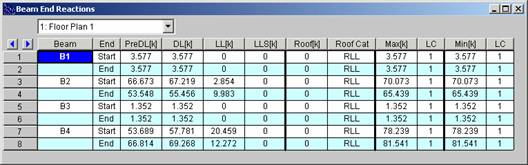
The End Reactions Spreadsheet records the end reactions for the beam elements and may be accessed by selecting End Reactions on the Results Menu. The pull down list at the top of the spreadsheet allows you to toggle between floors.
For hot-rolled steel members only load combinations with the "Connection" box checked on the Load Combinations spreadsheet will be used to calculate the displayed end reactions. See the Loads - Load Combinations topic for more details. All other beams' end reactions are based on their own material check boxes.
The sign convention assigns positive reactions to downward forces. Negative reactions, if they occur, would indicate uplift.
The Beam Label column displays the beam label.
The End column identifies for which end of the beam the reaction is being given, with the beam start and end on alternating rows.
Note
The PreDL column displays the member end reaction due to the pre-composite dead load. This includes the sum of the beam self weight, deck self weight, deck construction dead load and pre-composite dead load.
The DL column displays the member end reactions due to the total dead load. This includes the sum of the beam self weight, deck self weight, pre-composite dead load and post-composite dead load.
The LL column displays the member end reaction due to the live load. This includes the sum of the live load and live load reducible categories. The portion of this value due to Live Load Reducible has already been reduced, thereby resulting in a final design value which should be appropriate for connection design.
The Roof column displays the member end reaction due to the roof load. This is the maximum of the following load categories: Roof Live Load, Snow Load, Snow Load non-shedding, and Rain Load. The Roof Cat cell displays the controlling load category for the roof load end reactions.
The Max, Min and LC columns display the maximum and minimum end reactions and the controlling load combination in which they occur.
Note:
Vibration calculations are performed for beam members according to the requirements of AISC Design Guide 11: Floor Vibrations Due to Human Activity. For information on beam vibration calculations and results, refer to Vibrations - Floor Framing.